| we ship to: |                                      |
| we ship to: | |

In this guide we will explain how to replace the keyboard that failed or was damaged on MacBook Pro 13.
The process of changing a keyboard on other models can be totally different, make sure that you use this guide to change a MacBook Pro 13 laptop keyboard only. Keep in mind that the guide shows the keyboard change process on MacBook Pro 13 inch Retina display, model A1502, production year 2015.
Follow the instructions on how to replace a keyboard on a MacBook Pro strictly to avoid any damage that may interfere with normal keyboard operation.
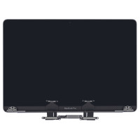
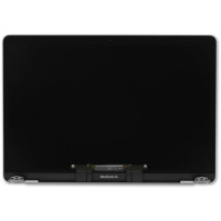
Also: How to replace a MacBook Pro screen

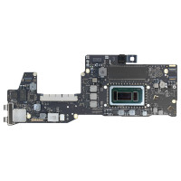
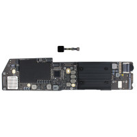
Genuine Top Case w/ Keyboard w/ Battery w/ Trackpad (661-02361) A1502 2015
Here you can find an example of changing Apple MacBook Pro 13”, Model A1502, keyboard. If you need to replace a keyboard of any other MacBook Pro model, search for the relevant guide or use this example as it shows the most crucial points to consider when you replace the keyboard of MacBook Pro. Internal components placement can differ, location and fixing methods, connector types may vary depending on the MacBook Pro model.
Attention! Using this guide for the keyboard replacement on any other models may lead to the severe damage of your device.
In a MacBook Pro the keyboard is mounted to the bottom side of the top case assembly. It means in order to replace the keyboard you will have to remove most internal components. You will need a set of fine Phillips and Torx screwdrivers.
You will have to remove the logic board and cooling fans, optical drive and un-route cables before you reach the keyboard.
You have to know the model year of your MacBook Pro in order to find the corresponding disassembly guide explaining how to replay the keyboard of MacBook Pro in detail. This is the most complicated part of the keyboard change process.
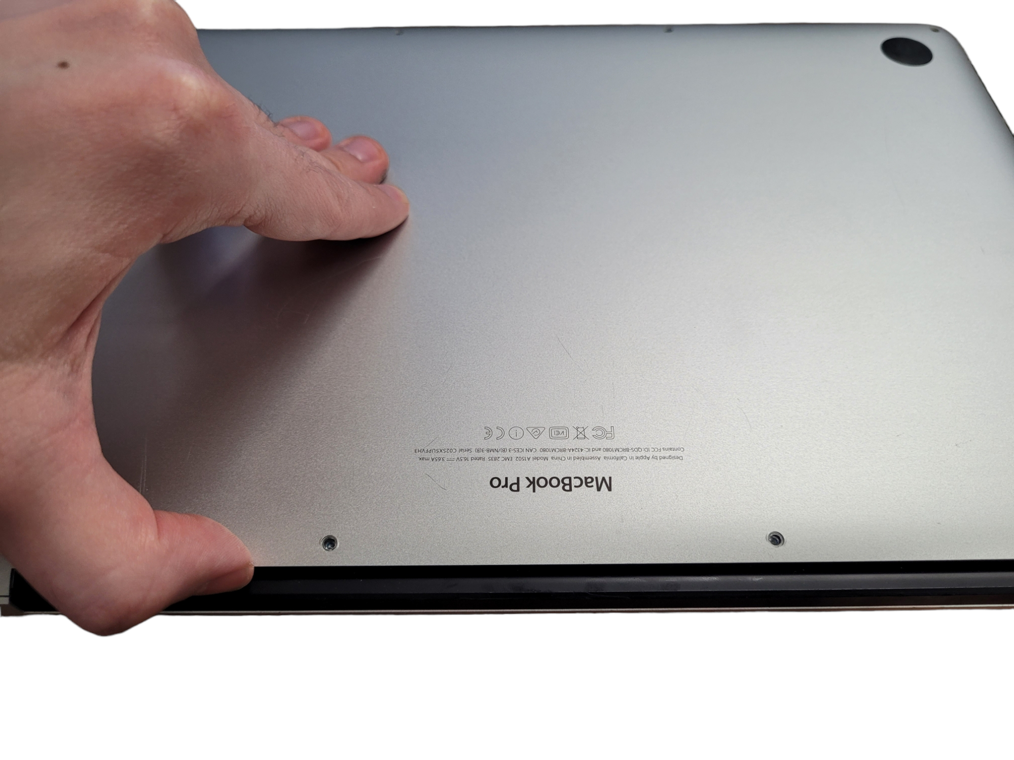
To make sure that the below keyboard replacement guide can be used for your MacBook Pro, you should carefully check the serial number and the model year of your device Serial number is printed on the bottom cover of your MacBook Pro. You can also check the serial number of your device on the Apple site.
When you find your device serial number, you will also find the model year, i.e. the production year. Like, for example, it can be shown as MacBook Pro (15 inch, Mid 2010)
It is NOT necessary to remove the battery, hard drive and display panel.
In case you remove the battery, do not re-use it, change it with a new one.
In this particular case of MacBook Pro A1502 model, uppercase assembly includes battery and trackpad thus you do not have to disassemble them to be changed.
Before you start the process, turn on your MacBook Pro and let the battery fully discharge. Charged lithium-ion battery can be dangerous and can cause accidental fire if punctured.
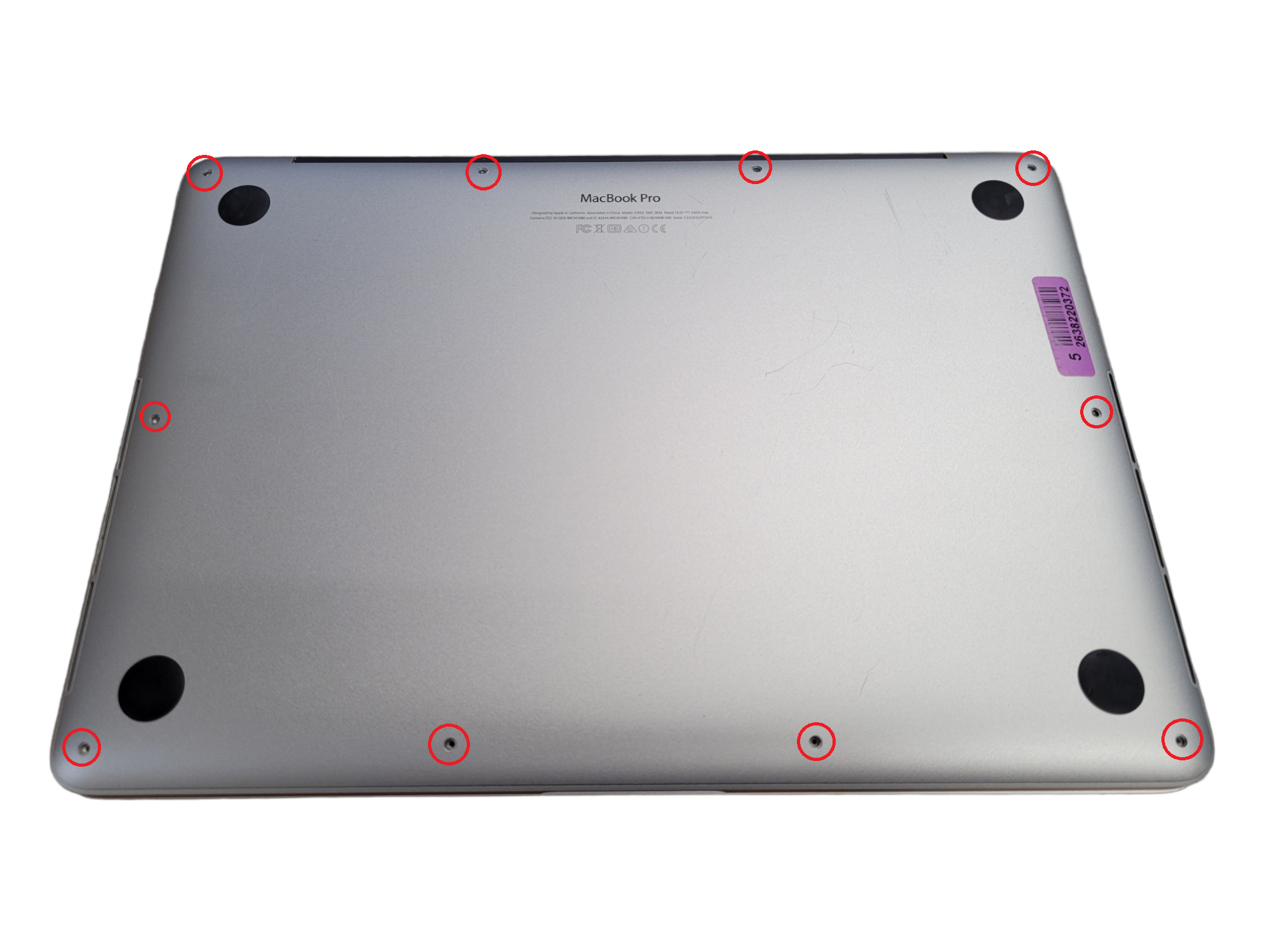
Remove the following 10 screws securing the lower case to the MacBook Pro 13" upper case: 2* 2.3 mm P5 Pentalobe screws. 8* 3.5 mm P5 Pentalobe screws.
Remove the lower case screws.
You can take a sheet of paper and draw the lowercase with the holes and screws for the job, also you can take and print out a pic and scotch tape the screws/brackets/cables you remove at each step next to the component descriptions. That way, when reassembling, the bits are placed right next to the photo of where they came from.
Magnetic mat to place the small details in the right order will also be of use if you have it.
Wedge your fingers between the lower and the upper case. Slightly pull the lower case from the upper to remove.
Slightly push down the center of the lower case to reattach the two plastic clips which connect the lower case to the upper case near its center.
If needed, remove the plastic cover adhered to the battery contact board.
Lift the battery connector straight up out of its circuit on the logic board using the flat end of the spudger.
Be sure that you lift up only the connector and not the socket as if you lift up the socket, it may severely damage the logic board.


Remove the two 2.1 mm T5 Torx screws that secure the logic board end of the I/O board cable bracket.

Remove the I/O board cable bracket.
Pop the I/O board connector up off the socket on the logic board. To do this use the flat flat end of a spudger.

Be careful to pry up on the I/O board cable only, not on the socket itself as it may damage the logic board.
Lift the logic board end of the I/O board cable straight up to bend it out of the way.
In order not to damage the cable, fold only at the bend in the I/O board end of the cable.
Carefully tuck the tip of a spudger under the right speaker cable near the connector and lift it up out of its socket on the logic board.

Carefully peel the right speaker cable off the upper case.
Remove the following screws that secure the right speaker to the upper case:

Lift the right speaker from the cable end and pull it free from the case.

Insert the tip of a spudger under the left speaker cable near the connector and lift it up out of its socket on the logic board.


Remove the following screws that secure the left speaker to the upper case:

Lift the corner of the left speaker up and slide it out around the battery to remove it from the upper case.

Be careful not to snag the speaker cable on the screw hole post in the side of the case.
Grasp the black plastic tab to flip the display cable connector open, pull it straight out of its socket on the logic board.
Make sure that you pull in the direction of the cable, parallel to the logic board. Do not pull it up.


Pull the DC-In board connector straight out of its socket on the logic board.

Remove the two 3.5 mm T5 Torx screws securing the MagSafe DC-In board to the upper case.
You may need to carefully push the display cable out of the way to make access to the screws.

Use the MagSafe DC-In board cable to pull the board out and up from the upper case to remove it.
Remove the rubber fan bumper from the edge of the heatsink carefully.

The fan bumper wraps around the heat sink and fits into slots in the fan duct. During reassembly, be sure to fit the tabs into the notches in the fan duct.
Peel the four foam stickers off of the heat sink screws using the flat end of the spudger.

Remove the following screws securing the heat sink:

Remove the heatsink from the laptop.

Use the tip of a spudger to push on either side of the iSight camera cable connector and take it out of its socket on the logic board step by step.
Peel the iSight camera cable up off the fan housing to fold it out of the way.
Remove the microphone cable from the upper case with the tip of the spudger.

Carefully pull the fan cable from its connector.

Remove the following screws securing the fan to the upper case:

Lift the end of the fan from the heatsink cavity and pull it up and out toward the hinge of the laptop to remove.
Insert the tip of a spudger under each of the antenna cables near their connectors and pry up to disconnect them from the AirPort board.

The three cables are coded with black sleeves of different lengths.
During reassembly:
When reconnecting the antenna cables, run them over the camera cable, not underneath.
With the tip of a spudger, push on either side of the I/O board connector to take it out of its socket on the logic board carefully, step by step.

Remove the following screws securing the I/O board to the upper case:

Lift the I/O board cable end of the I/O board and pull toward the logic board to free the ports from the upper case.
Remove the I/O board.

When reinstalling the I/O board, be sure to slide the USB ports' metal EMI fingers under the side of the case, not over.
Use the flat end of a spudger to disconnect the keyboard backlight cable and move it out of the way.

Peel back any tape covering the microphone cable ZIF connector if necessary.
Use the tip of a spudger to flip the retaining tab on the microphone cable ZIF connector.
Pull the microphone cable straight out of its socket on the logic board.


If necessary, peel back any tape covering the keyboard cable connector.
Use the tip of a spudger to flip the retaining tab on the ZIF connector.
Pull the keyboard cable straight out of its ZIF socket on the logic board.


Remove the five 3.5 mm T5 Torx screws securing the logic board to the upper case.

When reassembling, install all five screws loosely, position the logic board, and then tighten evenly.
Lift the processor end of the logic board up slightly and pull it toward the fan recess to free the ports from the edge of the upper case and remove the logic board.
When reinstalling, make sure the keyboard, keyboard backlight, and microphone cables don't get trapped beneath the logic board.
Also be sure to slide the ports' metal EMI fingers under the side of the case, not over.

Use a pair of tweezers to lift the rubber hinge covers up off the right and left display hinges.

Remove the 3.2 mm T5 Torx screws (one on each side) which secure the aluminum hinge brackets to the upper case.


Remove the four inner 5.3 mm T8 Torx screws (two on each side) which secure the display to the upper case.

Open the MacBook Pro a little wider than 90 degrees, and place it on end.

While holding the display and upper case together with your left hand, remove the remaining T8 Torx screw from the lower display bracket.


Be sure to hold the display and the uppercase together with your left hand. If you do not do so, the unattached display/upper case may fall, which will damage each component of your MacBook Pro.
Remove the last remaining T8 Torx screw securing the display to the upper case.
Grasp both halves of the device, one in each hand.
Gently push forward on the bottom half of the device to detach it from the display assembly.
Carefully put each component aside, making sure to set the lower half keyboard-side down.
If you change the keyboard by yourself, the only expenditure will be the price of the keyboard. The approximate cost is $99.
In case of a genuine top case with keyboard with or without the battery and trackpad, the price will be from $169.99 to $19.99 depending on the model and inbuilt battery and trackpad.
Attention! Make sure that you use original parts only! The best way to find the appropriate MacBook Pro original parts is to visit AppleParts.io.

|
ABOUT THE AUTHOR
Volodymyr Chubei Volodymyr was born in Ukraine and has found his passion for electronics from his childhood. At the age of 13, he was capable of soldering some basic elements of a logic board and today he is one of the co-founders of MacNest.com |
 review")
In this article, we will tell you which updates the new MacBook Pro model f...
Read More
-200x200.jpg "MacBook Pro 2018 vs MacBook Air 2020: which should you buy")
In this review we compare two Apple products: 2018 MacBook Pro vs 2020 MacB...
Read More

SSD or Solid State Drives are widely used nowadays. These drives are charac...
Read More

Apple is planning to launch a new laptop model- the 15-inch MacBook Air. Th...
Read More