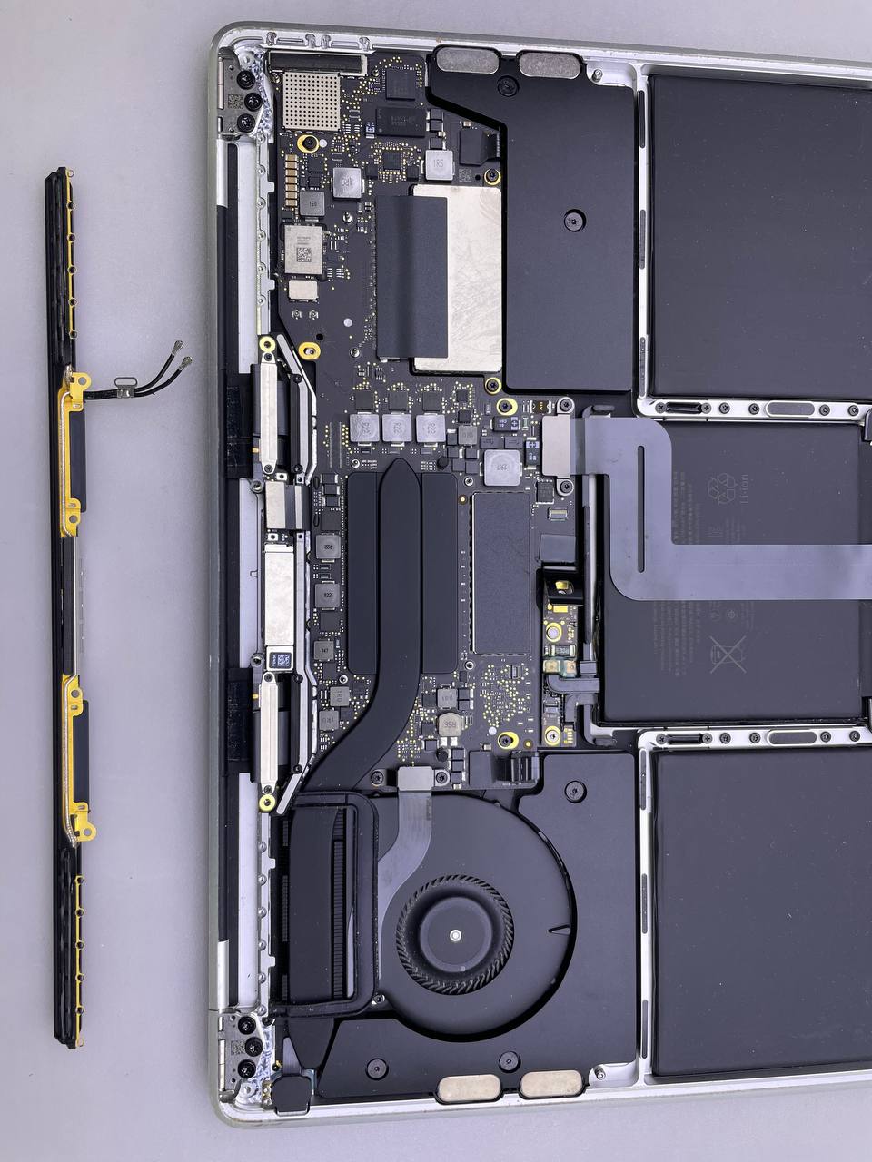
Use this guide to replace the display assembly of your MacBook Pro 13" A1708 2017
How to replace MacBook Pro 13 A1708 2017 Display: step-by-step guide
Use these instructions to replace the display assembly on your
MacBook Pro
without a Touch Bar (13-inch, 2017, Two Thunderbolt 3 ports).
You may want to check Apple to see if you qualify for a free repair before beginning this process. Your MacBook Pro can qualify for Apple's display backlight servicing programme if the backlight on display has ceased operating or if the screen has bright vertical areas running along the bottom of display (also known as "stage lights").
Before starting
repairs
, discharge the battery on your MacBook Pro to less than 25% of its capacity for your safety.
Also:
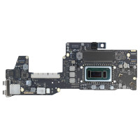
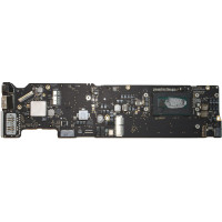
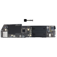
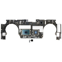
MacBook Pro A1708 Logic Board Replacement
.png)
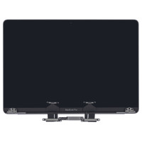
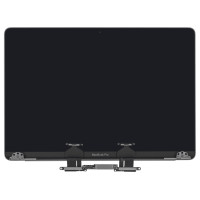
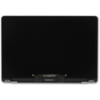
Genuine LCD Screen (Display) Assembly, Silver (661-05096) A1708 A1706
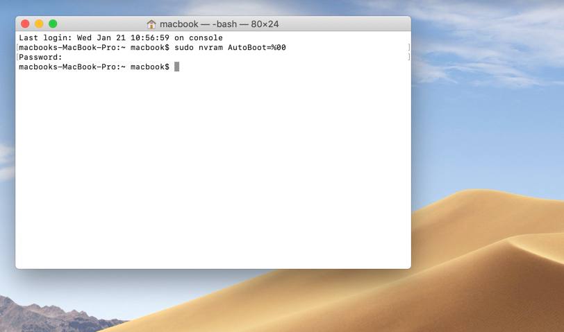
Step 1 Turn off the auto boot
- You must turn off your Mac's Auto Boot function before beginning the process. Your Mac turns on automatically when you lift the lid, and it can turn on accidentally during disassembly. To disable Auto Boot feature, read this article or the brief instruction below. On some Macs, this command may not work.
- Launch Terminal after turning on your Mac.
- Copy and paste the following command(or typed exactly) into Terminal:
nvram AutoBoot=%00 with sudo
- Press the Return key. Enter the administrator password if required, then press [return] key one again. Note: Your return key may also be labelled "enter" on it.
- Now when your Mac is securely powered down, you may open the bottom case without accidentally powering on.
- Use the following command to re-enable Auto Boot when repair is complete, and your Mac has been successfully assembled:
nvram AutoBoot=%03 with sudo
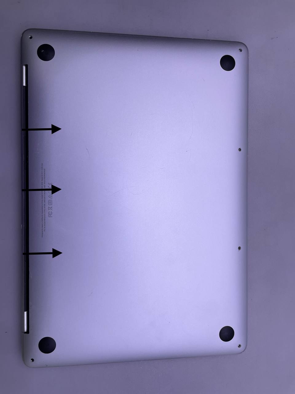
Step 2 Lower Case
Next step for Apple MacBook Pro 13 A1708 2017 display replacement.
Before proceeding, unplug and power down your MacBook. Close the display and lay it on a soft surface, top-side down.
- For the six screws securing the lower case in place, use a P5 Pentalobe driver as follows:
- Two 6.2 mm screws
- Two 5.3 mm screws
- Two 3.4 mm screws
To avoid damaging your device during repair, keep track of each screw and ensure it is placed back exactly where it came from.
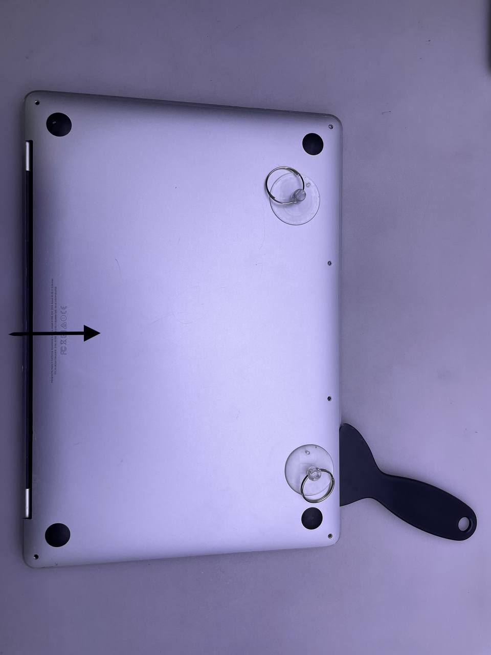
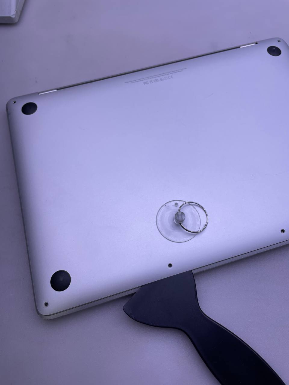
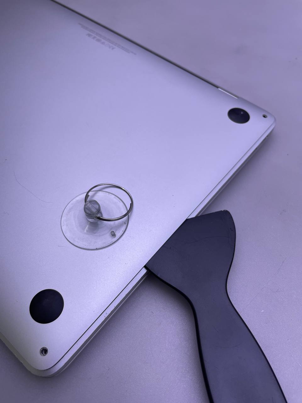
Step 3 Separate the lower case from the chassis
- Place a suction handle on the lower casing of the MacBook Pro's front-centre part.
- Lift the suction handle to slightly separate the lower case and the chassis.
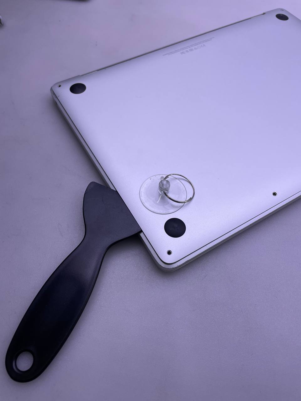
Step 4 Release the first of the hidden clips
- The lowercase should be placed between the chassis and the opening pick's corner.
- The side of the case is halfway up; slide the opening pick around the nearest corner.
This releases the first of the hidden clips securing the lower case to the chassis. You should feel and hear the clip pop free.
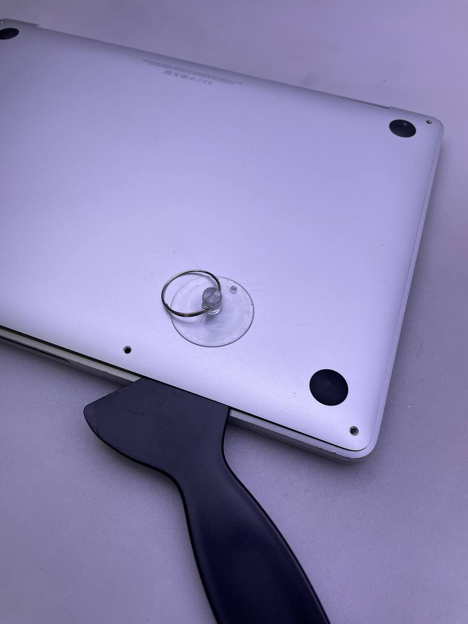
Step 5 Release the second clip
- To release the second clip, repeat the previous step on the opposite side, sliding your opening pick beneath the lowercase and up the side.
Step 6 Release the third and fourth clips
- Insert your opening pick again close to one of the two centre screw holes under the front edge of the lowercase.
- Firmly twist the pick to release the third clip securing the lower case to the chassis.
- Repeat the procedure near the other of the two centre screw holes to pop the fourth clip free.
Step 7 Release the final clip
- To release the last clip securing the lower case together, pull the lower case firmly toward the front of the MacBook (away from the hinge area).
- Pulling at one corner first, then the other.
This may require a lot of force.
Step 8 Remove the lower case
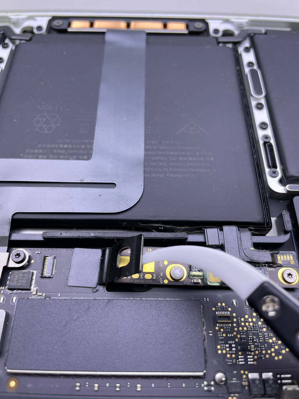
Step 9 Battery Connector
- On the edge of the logic board closest to the battery, carefully remove a large piece of tape covering the battery connector.
- Take the tape off.
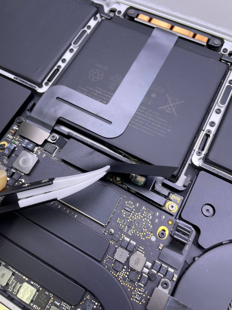
Step 10 Remove the little piece of tape covering the data cable connector on the battery board
- Carefully remove the little piece of tape covering the data cable connector on the battery board.
The tape is integrated into the ribbon cable and won't be detached completely. Peel it back just enough to get to the connection.
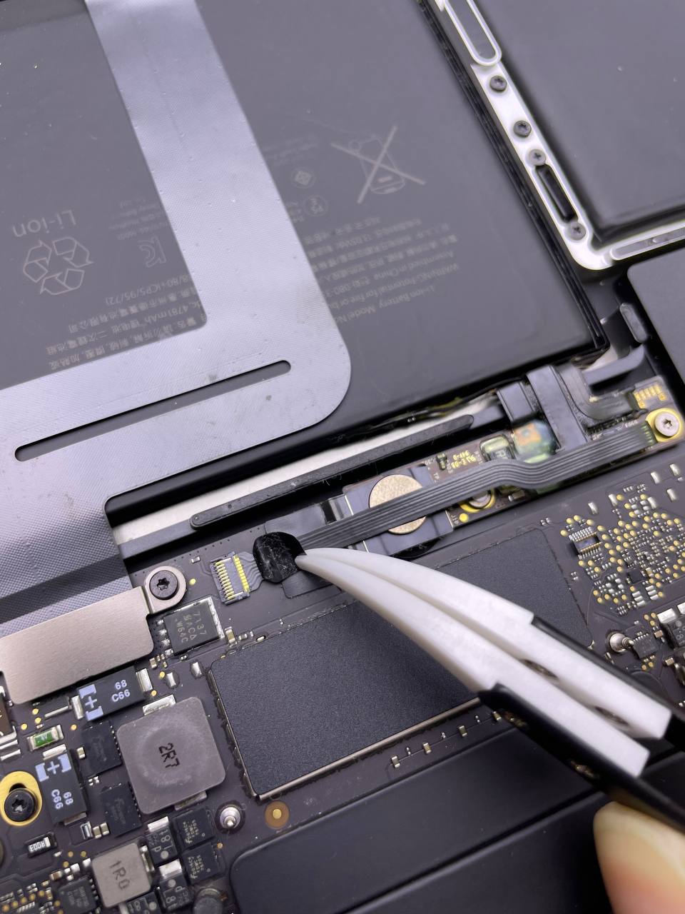
Step 11 Flip up the locking tab securing the cable in its connector
- Flip up the small black locking tab securing the cable in its connector using the tip of a spudger.
Step 12 Slide the data wire for the battery board to disconnect it from the socket
- Slide the data wire of the battery board out of its socket to disconnect it.
- Slide parallel to the logic board and in the cable's direction.
Step 13 Fold the data cable for the battery board back and out of the way
- Fold the data cable for the battery board back and out of the way.
You might need to completely remove and transfer this cable to your new battery if you're changing your battery. The cable should be carefully removed after severing the ends. Be cautious not to put it backwards or upside-down during installation; see the orientation in the photos.
This is an important step for MacBook Pro 13 A1708 2017 display replacement.
Step 14 Use a T5 Torx driver
- To remove the 3.7 mm pancake screw securing the battery power connection in place, use a T5 Torx driver.
Step 15 The battery may be disconnected
- The battery may be disconnected by carefully lifting the battery power connection with a spudger.
- Lift the connection off of the socket high enough to keep it separated from its socket. During the course of your repair, it might accidentally make contact and damage your MacBook Pro.
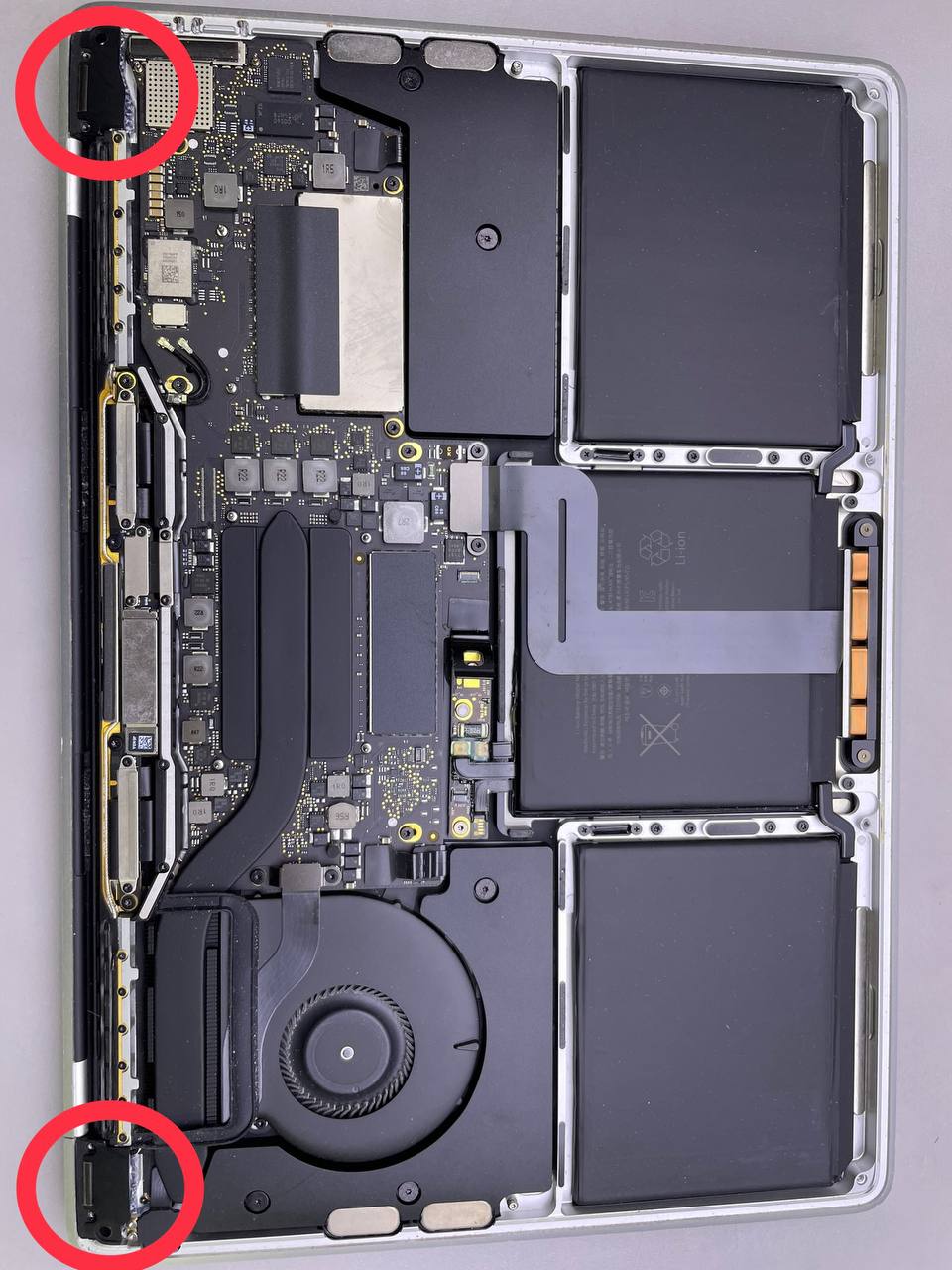
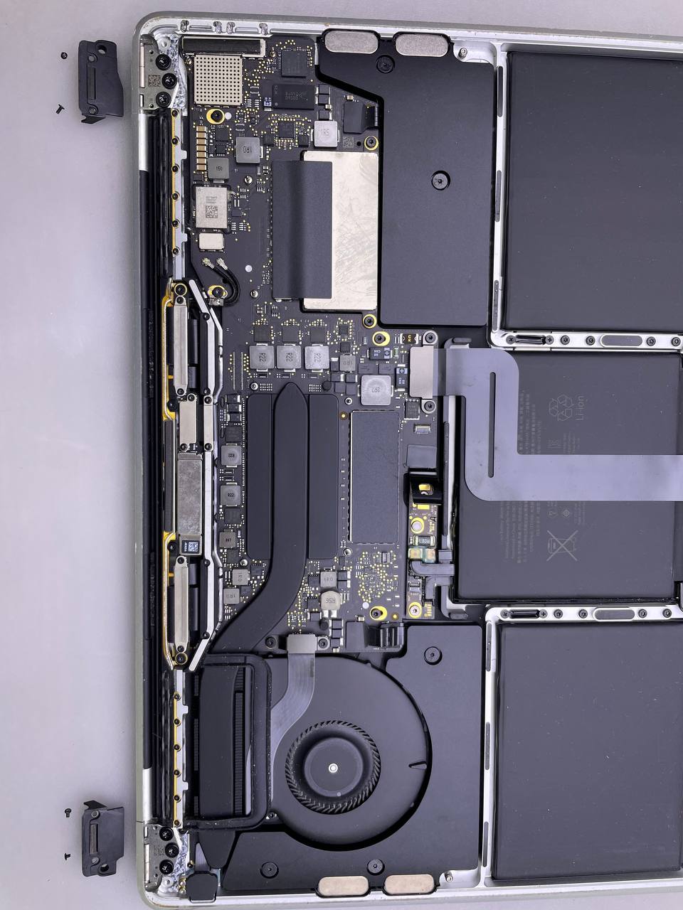
Step 16 Remove the hinge covers
-
The four 1.9 mm T3 Torx screws securing the plastic covers over the display hinges in place must be removed.
-
Remove the two plastic hinge covers.
Step 17 Disconnect the main display cable
- The two 2.9 mm T3 Torx screws securing the aluminum cover on top of the display cable must be removed.
- Remove the cover.
Step 18 Remove the cover
- The two 1.7 mm T3 Torx screws securing the aluminium cover on top of the display cable flex connection must be removed
- Remove the cover.
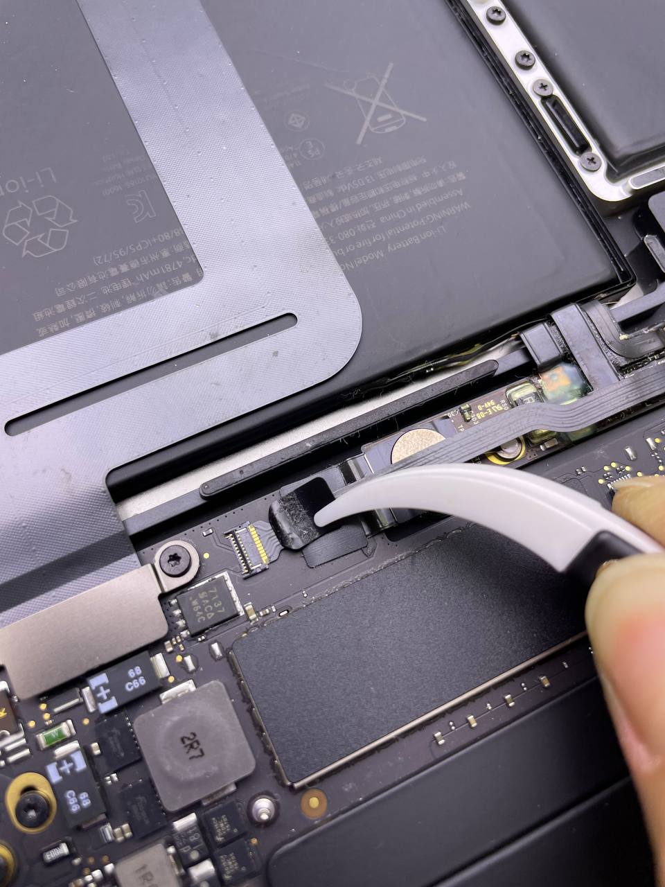
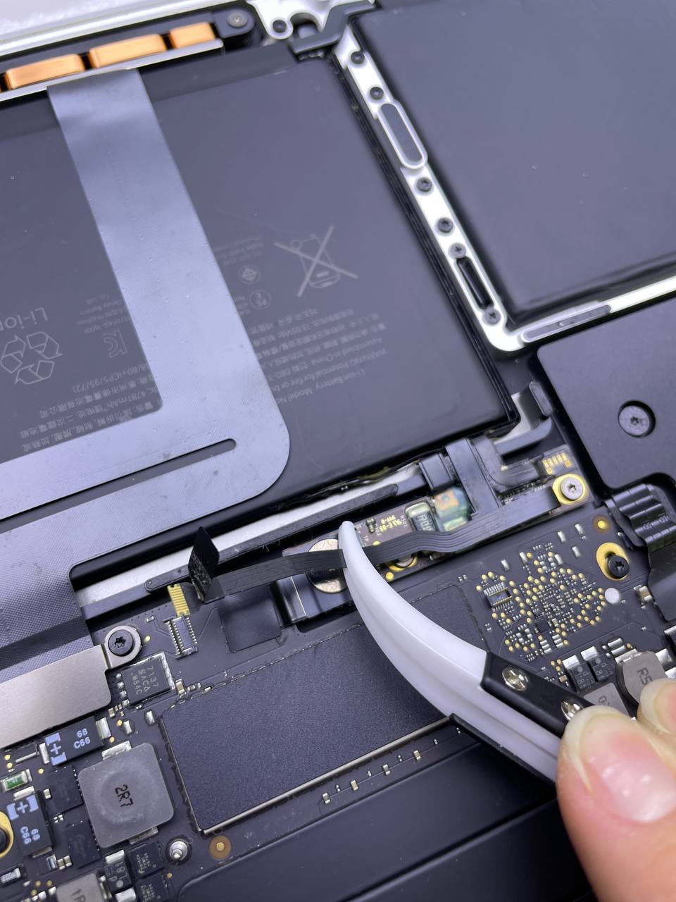
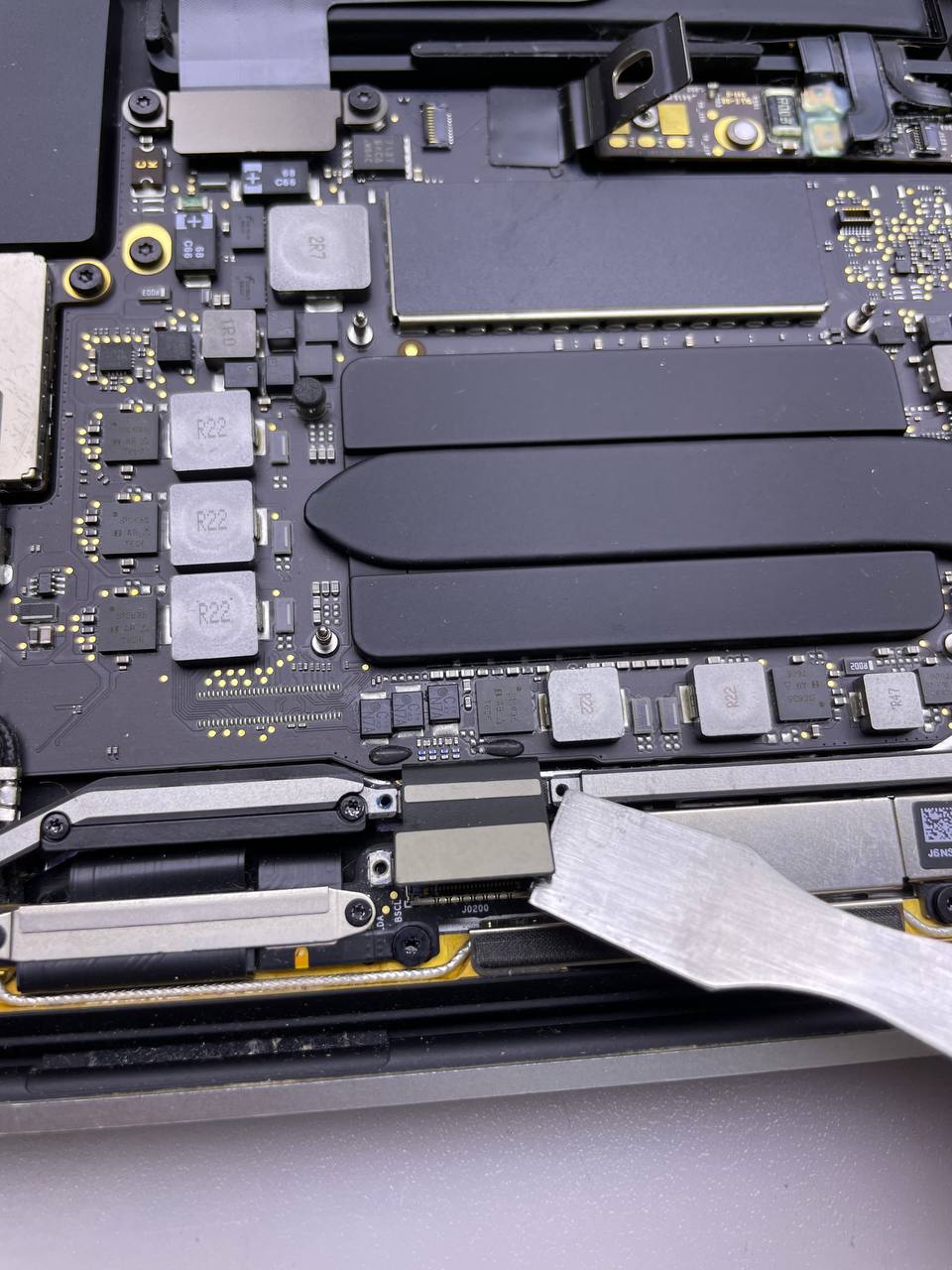
Step 19 Pry the cable straight up from its socket
- To disconnect the display board flex cable from the display board, pry the cable straight up from its socket.
Step 20 Remove the cover above the display cable
- Take out the four 1.5 mm T3 Torx screws securing the two aluminium covers over the two display wires
- The two aluminium covers may be removed using a pair of tweezers
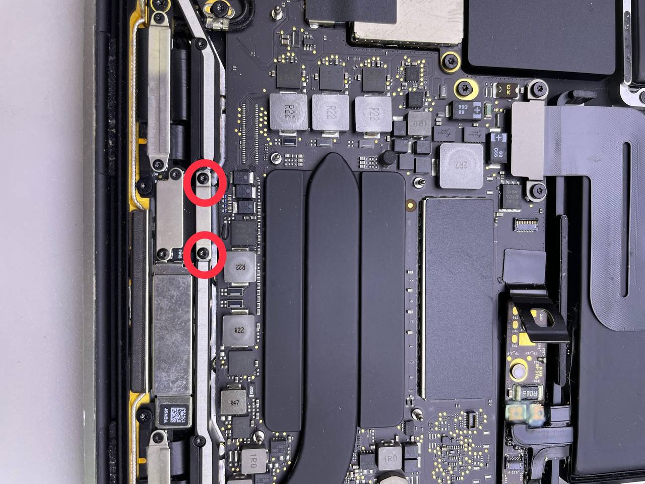
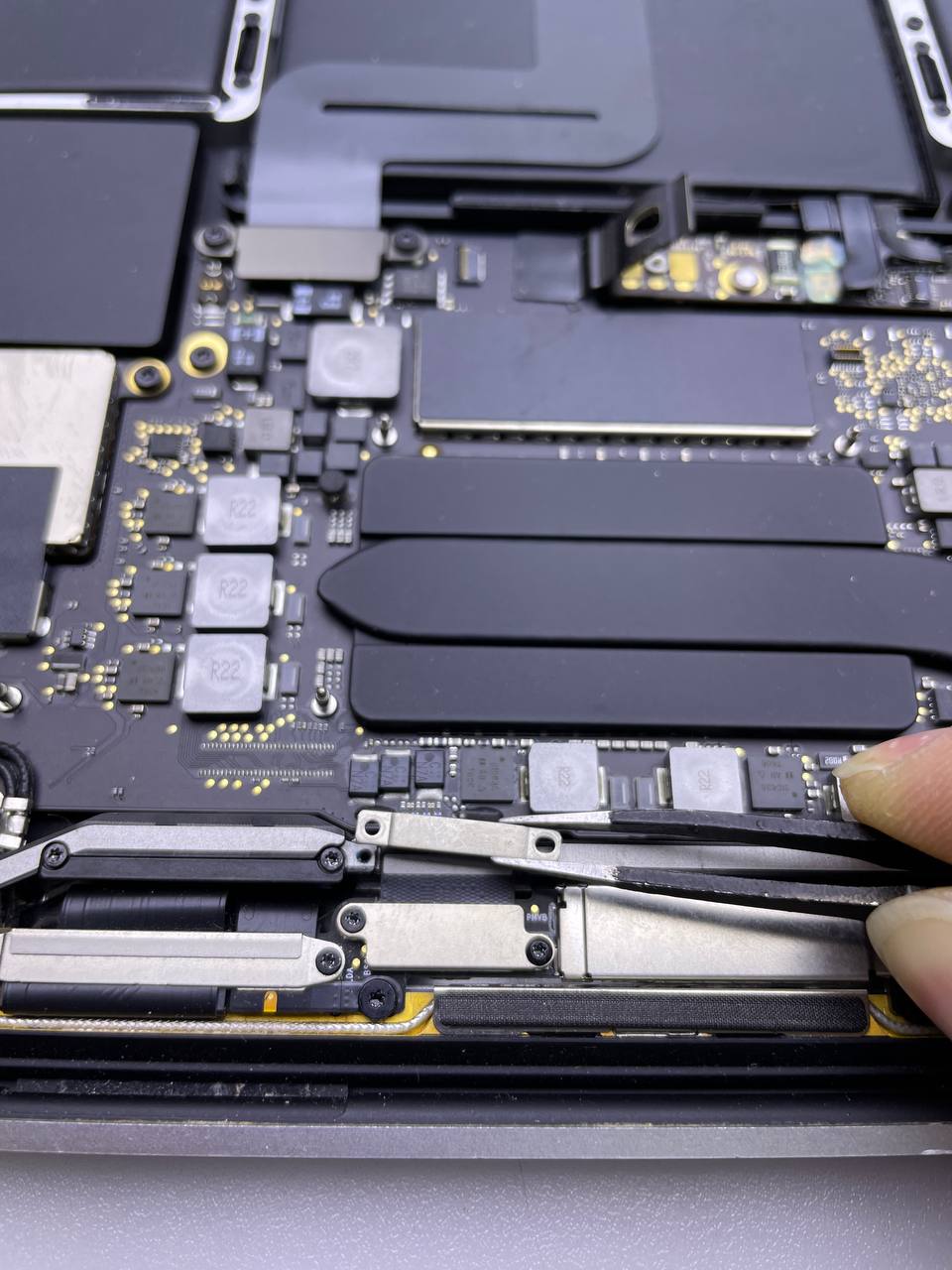
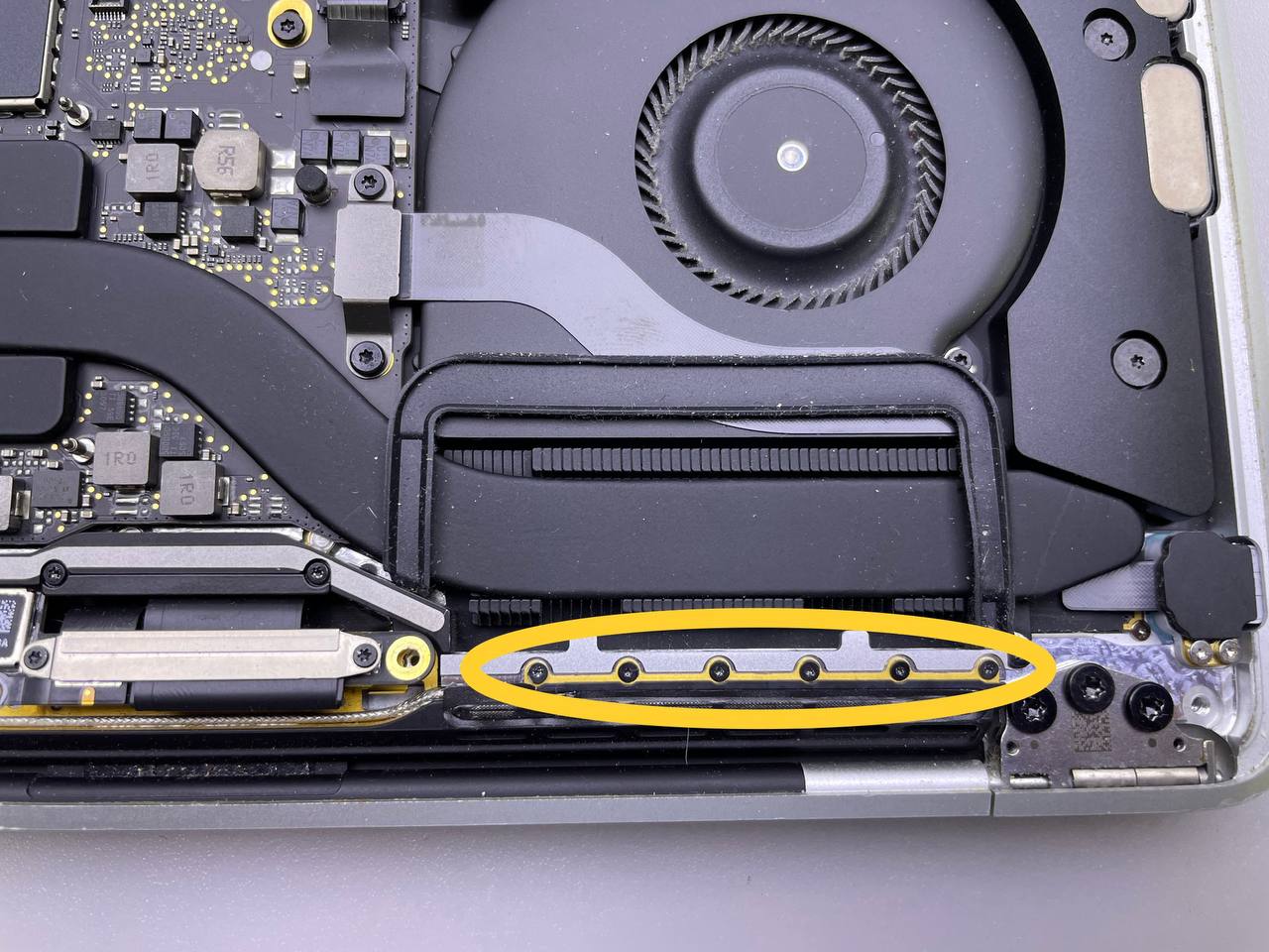
Step 21 Unscrew the antenna assembly's
- Remove the two 3.3 mm T5 Torx screws securing the antenna cable assembly (one from each side).
- Remove the two 4.1 mm T5 Torx screws as well (one from each side).
- Remove the twelve 1.1 mm P2 pentalobe screws securing the remaining antenna cable assembly(six from each side).
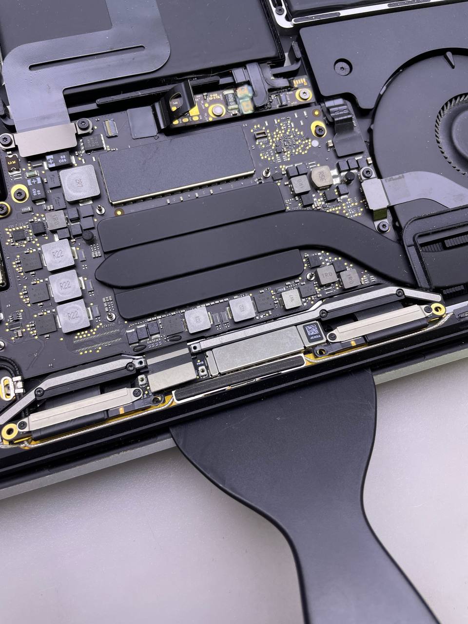
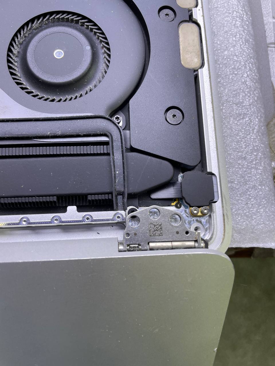
Step 22 Disconnect the antennas
- Pry the two coax cables for the antennas straight up from the logic board.
- Carefully twist or pry up with your tweezers or spudger on each cable until it is near the socket.
- Align the connection directly over the socket on each cable, then press down until the connector securely snaps into place.
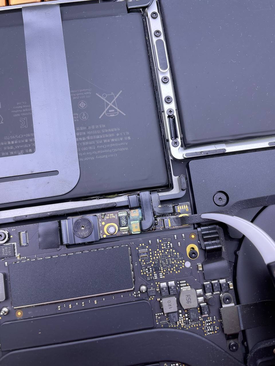
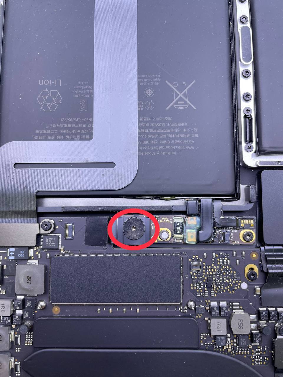
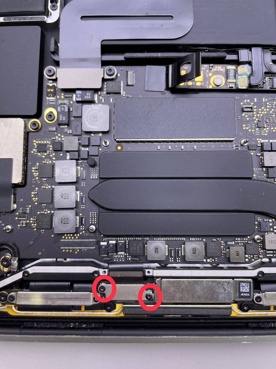
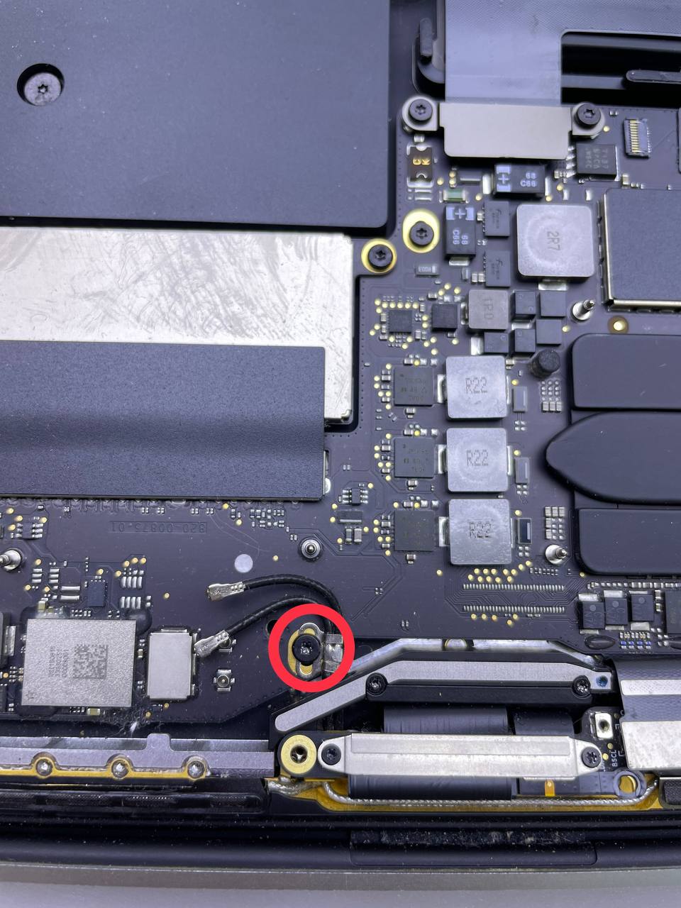
Step 23 Remove the 2.8 mm T5 Torx screw
- Remove the 2.8 mm T5 Torx screw securing the two antenna coax cables to the main board.
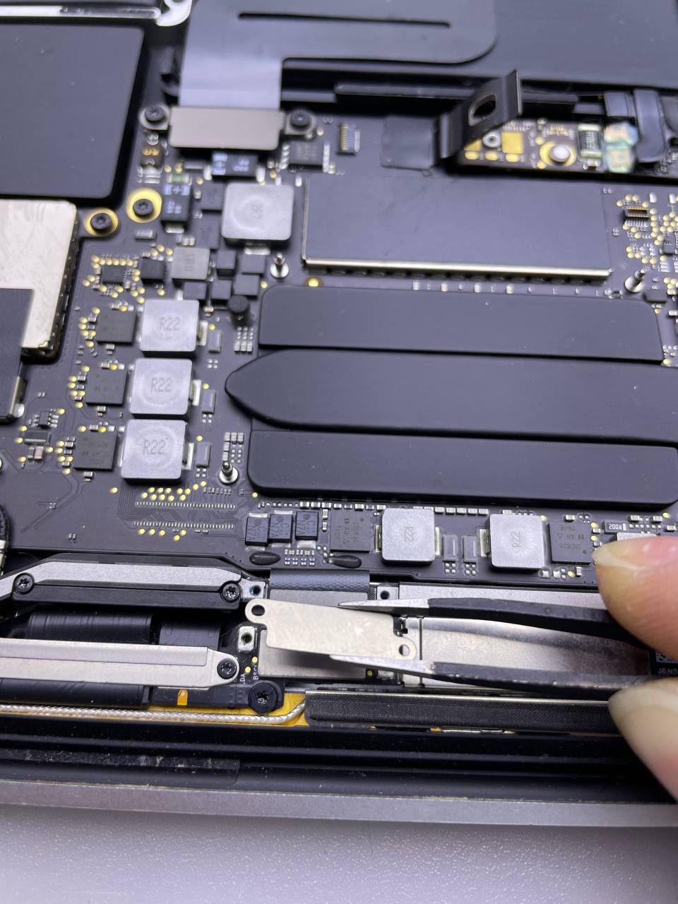
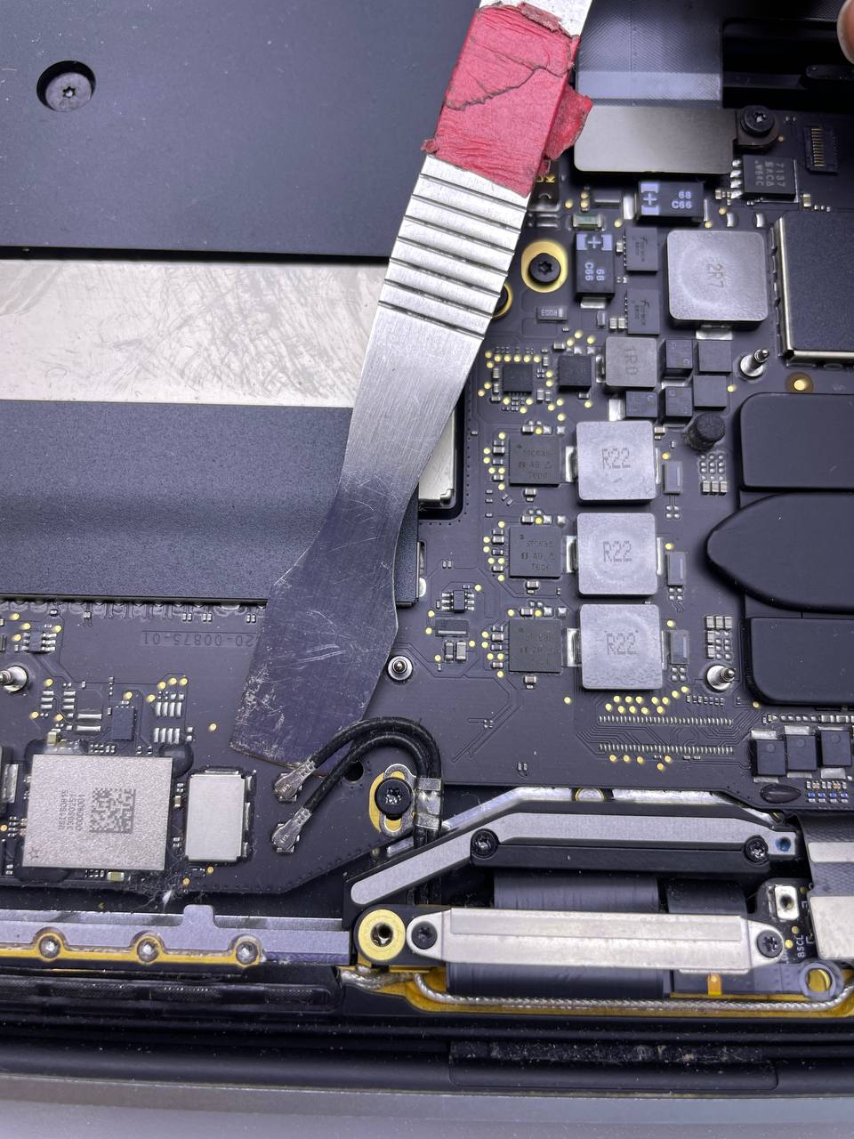
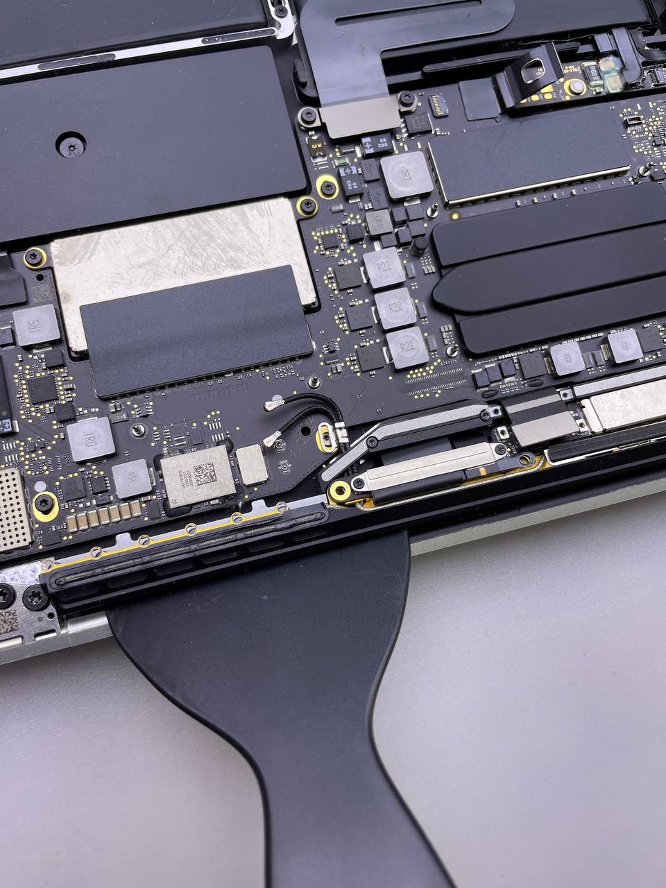
Step 24 Unseat the antenna assembly
To disconnect the antenna cable assembly in the indicated areas, use an opening pick.
- Don't slide the opening pick from side to side, as there are two display cables in the way that may be damaged.
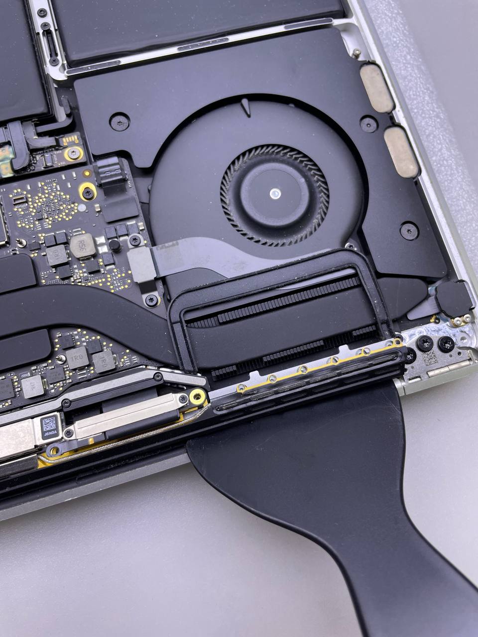
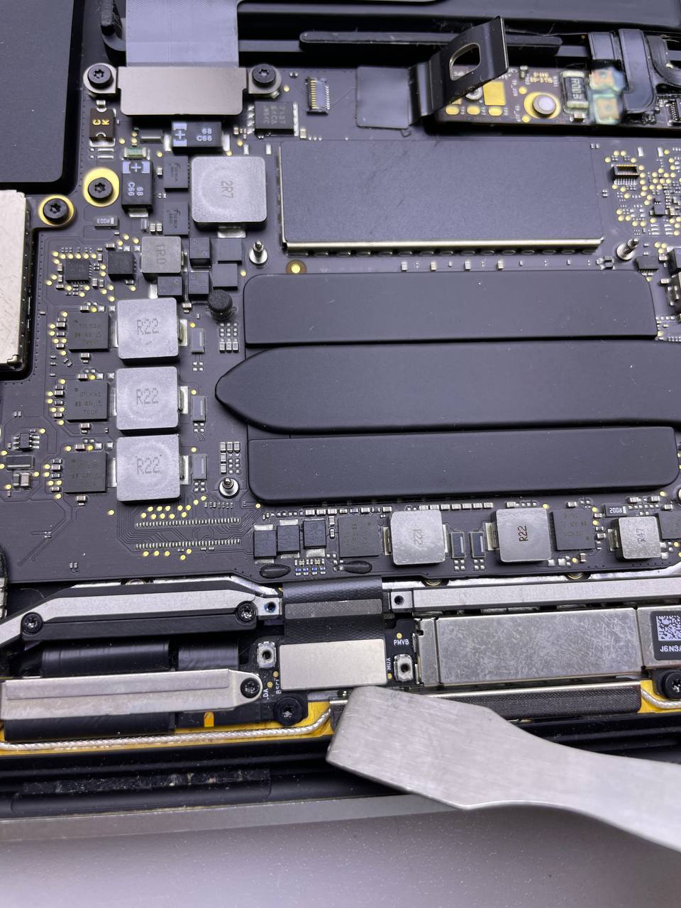
Step 25 Remove the antenna assembly apart
- While simultaneously feeding the antenna cable bundle through the hole in the chassis, carefully remove the antenna assembly.
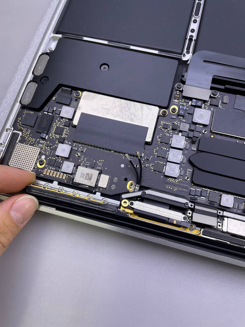
Step 26 Take apart the antenna cable assembly
- Remove the antenna cable assembly.
- Gently pinch the cable bundle together during reassembly, and then guide it through the hole in the chassis and onto the board's proper location. If necessary, guide it using your tools; do not push or force it through.
Keep this in mind when replacing the MacBook Pro 13 A1708 display assembly.
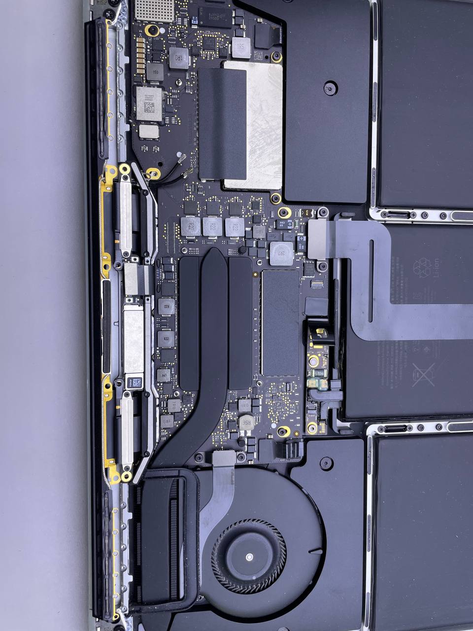
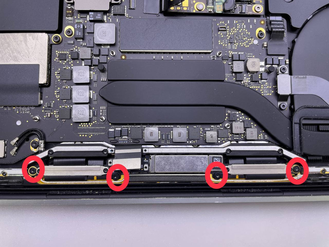
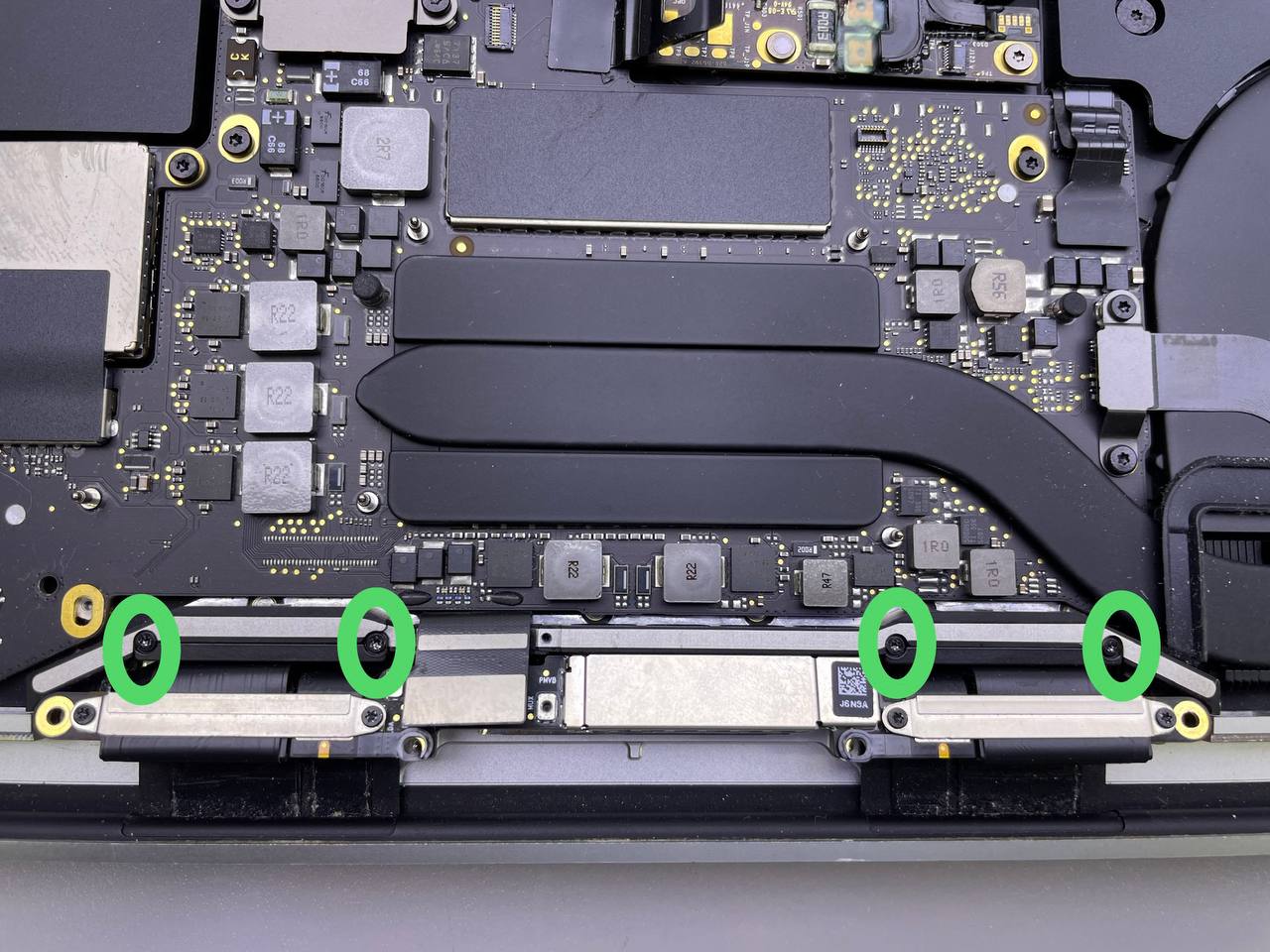
Step 27 Remove the display cable assembly's screws
- Four 3.9 mm T3 Torx screws that secure the cover springs on the two display wires can be removed.
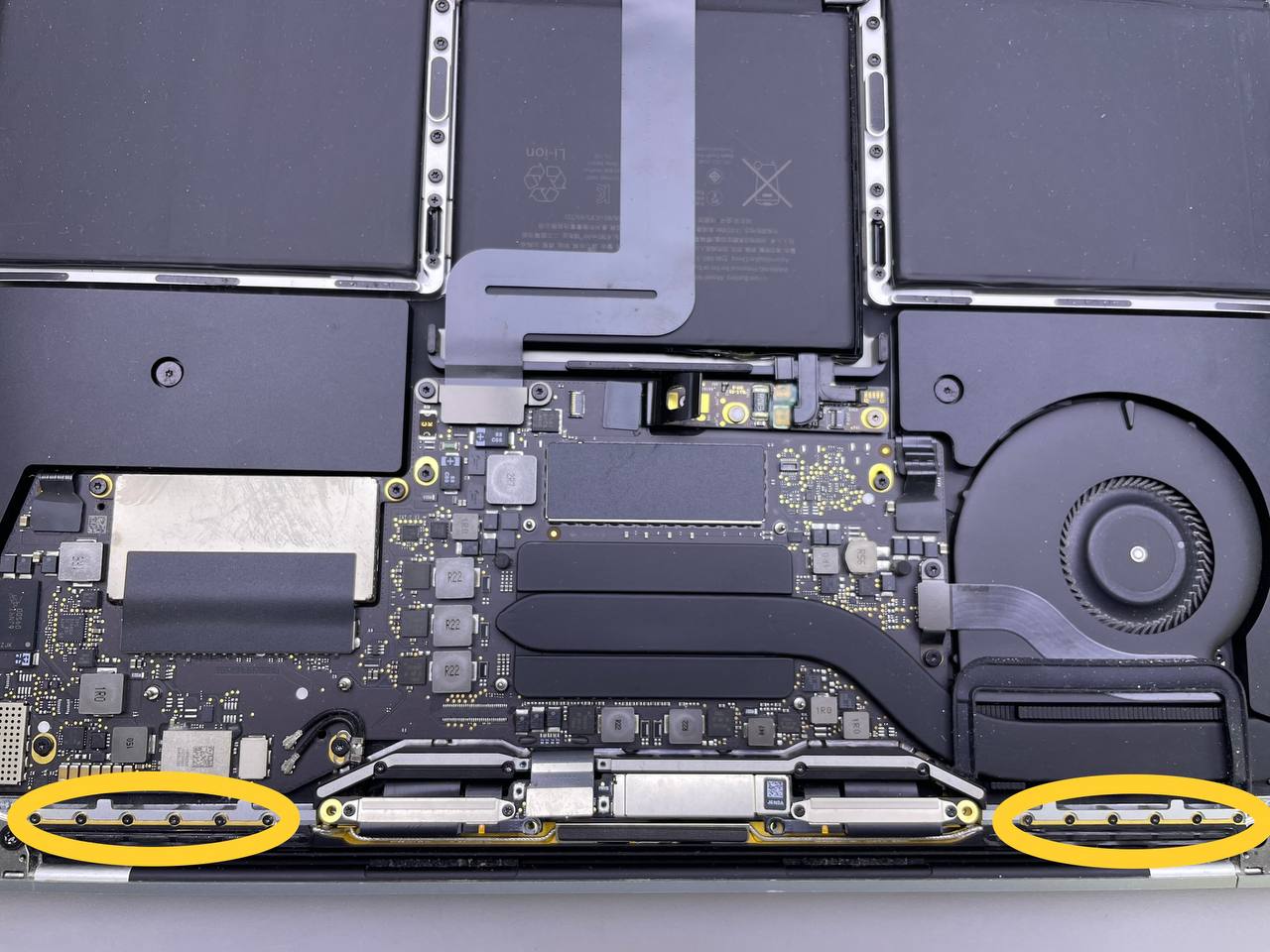
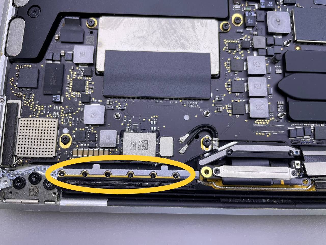
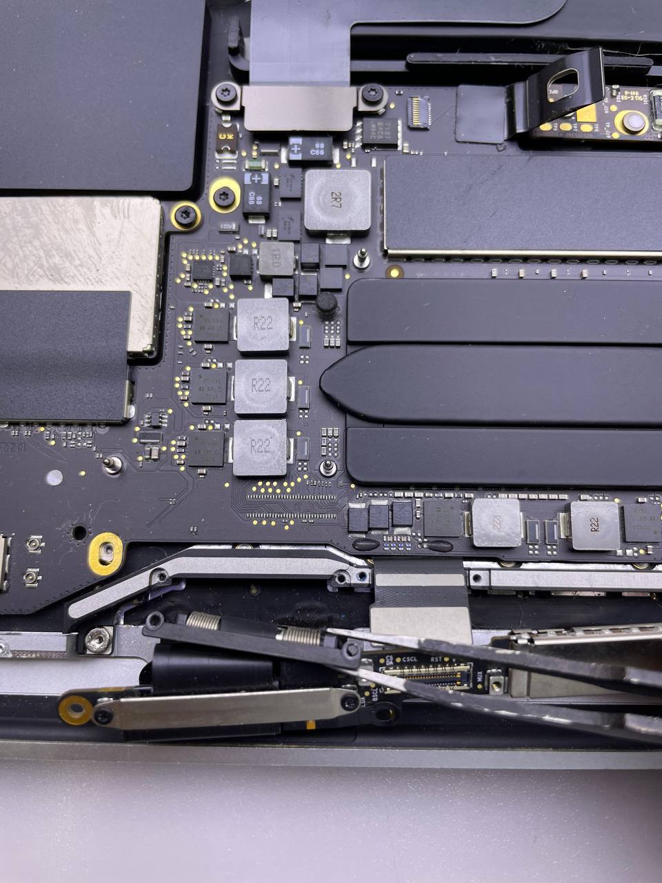
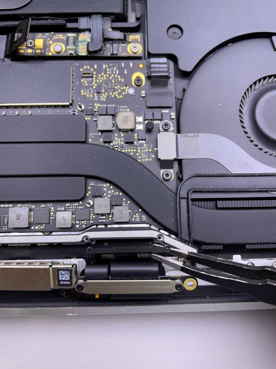
Step 28 The display cable assembly must be removed
- Take the left side of the display cable assembly, move it away from the cover spring and pull toward the bottom end of the MacBook.
- With a pair of tweezers, remove the cover spring from the display cable's recessed area.
- Repeat the step again with the right cover spring.
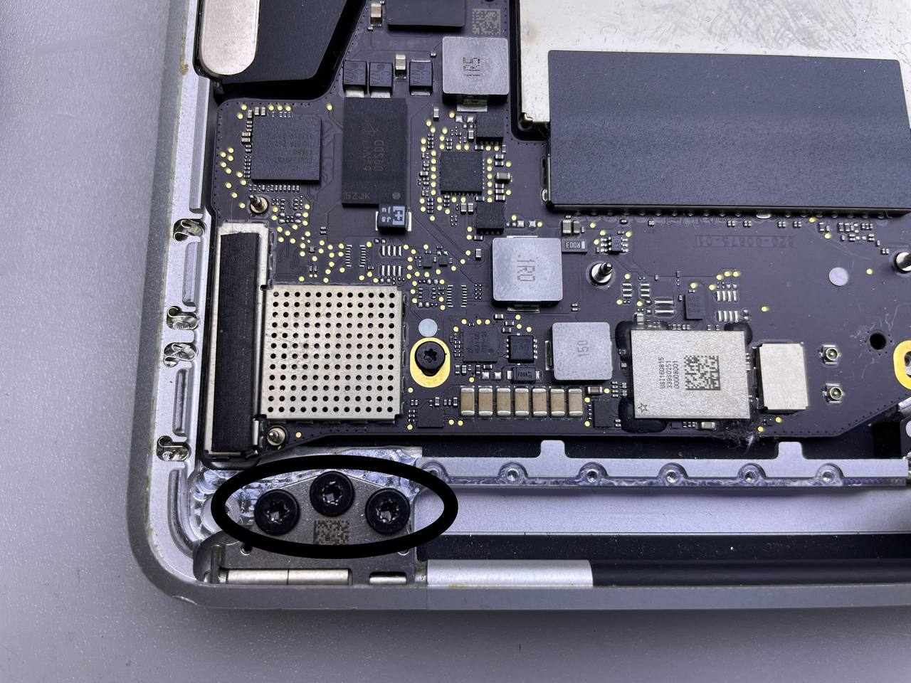
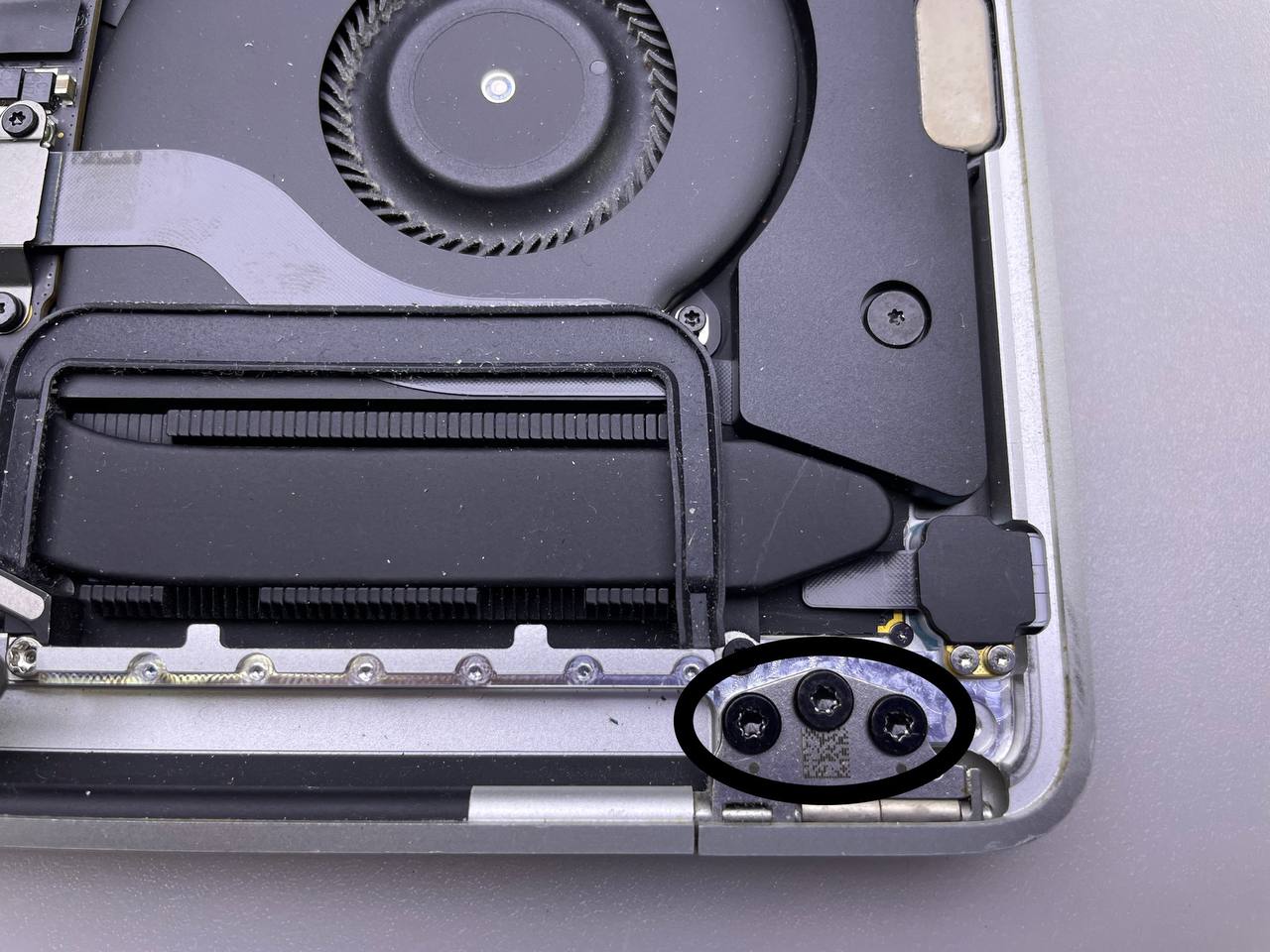
Step 29 Unscrew the hinge bolts
- Open the screen fully and place your MacBook Pro on one side.
- Remove the three T8 Torx screws from the lower display hinge while holding the MacBook Pro firmly with your free hand.
- Remove the remaining three T8 Torx screws from the upper display bracket.
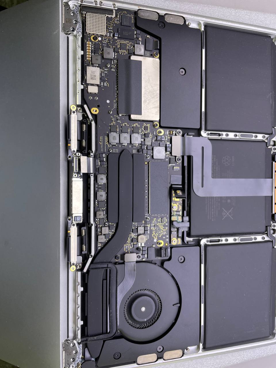
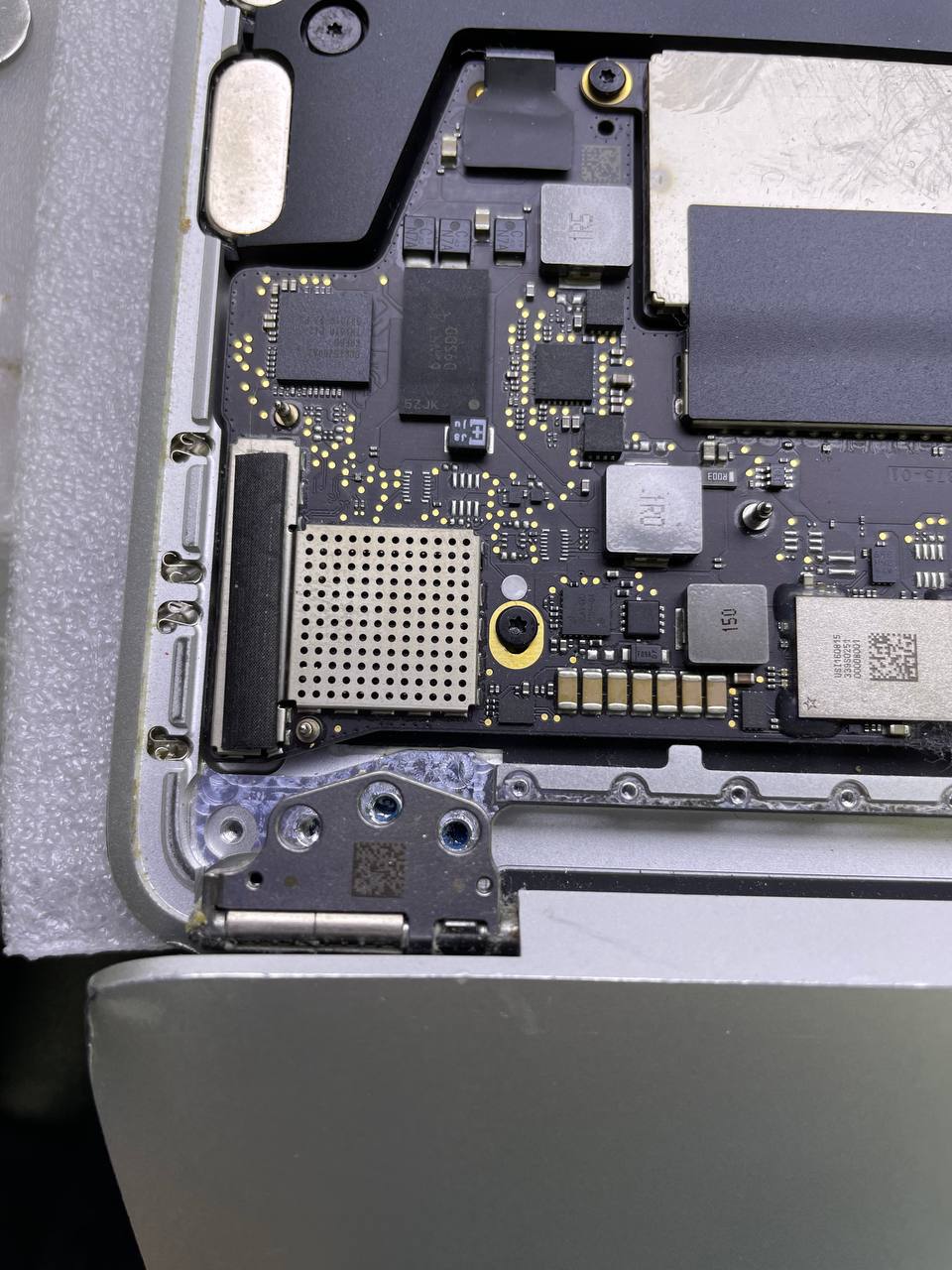
Step 30 Completely remove the display assembly
Keep a firm grip on both the screen and the main body of the MacBook Pro. Either half can fall unexpectedly during this step.
- Push both halves of the MacBook Pro's together to allow you to remove the hinge brackets from the chassis recessed areas.
- To remove the screen from the main body of the MacBook Pro, push the body of the computer away from you.
- Carefully remove the display and screen assembly, being mindful not to snag it on any cables. During reassembly, ensure the display cable assembly lies on the correct side of the main body before refastening the hinge bolts.
- As they might have come loose during the disassembly procedure, be sure to double-check that both connections on each side of the display cable assembly are fully seated.
We explained to you how to replace the MacBook Pro 13 A1708 display assembly. You can find the necessary parts on our website.